
Swiss turned parts live in a specific tolerance world. Their geometry is generated around an axis, the bar feeds through a guide bushing, and the features that matter are the diameters, the circular forms, and the relationships between features along that single centerline. A buyer specifying such a part is writing in the language of rotation, and reading the drawing back requires the same language.
The practical bands are familiar, but the geometry language is what separates a good turned-part drawing from one that produces arguments at the first article.

What tolerance language matters most on a turned part?
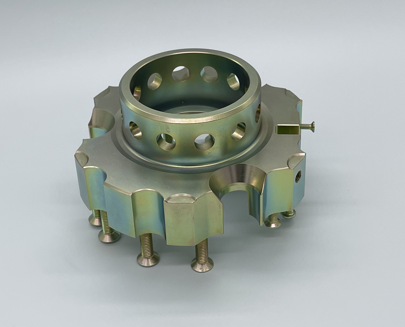
The tolerance language of a turned part is the language of its geometry: rotation. Diameter tolerances control the sizes that mate or seal; roundness controls the circular form of a cross-section; cylindricity controls the form along the axis, combining roundness with straightness; and concentricity or run-out control the relationship between features that share the centerline. A turned part is defined by its axis, and the callouts that matter are the ones that control features around and along that axis.
Writing this language correctly means expressing the critical features against a datum frame built on the turned geometry. The datum is the axis or the functional shoulder the part locates from, and every tight callout — the position of a cross hole, the run-out of a bearing seat to the main diameter — is expressed against it. A drawing whose datums are the turned features is a drawing the CMM can measure and the assembly can repeat; one whose datums sit on convenience features is a drawing that will be argued about at inspection.
The language also tells the shop where the process attention goes. A drawing with three controlled diameters, a roundness callout on one, and a run-out between two of them is a drawing that names its risk; the shop can plan the cuts, the checks, and the report around those three features. The buyer who speaks the rotational language fluently writes drawings that the shop can execute without interpretation, and that fluency is worth more than any single band on the drawing.
Which diameters carry the tight bands on swiss work?
The diameters that earn tight bands are the functional ones: the seat that carries a bearing, the journal that runs in a bore, the seal diameter that must hold a controlled fit, and the pitch diameters of threads that carry load. These features control the part's behavior in its assembly, and their bands are set by the function rather than by a blanket rule. General diameters — the body of the part, the cosmetic steps, the clearance sections — run at the block tolerance, because a tight band on a diameter that does nothing adds inspection cost without adding function.
Swiss-type machines hold ±0.002 mm on controlled diameters as standard practice, with the guide bushing giving the slender work the support it needs. The tightest practical bands belong on the features the assembly depends on, and they should be marked so the inspection measures exactly those diameters through the run. A drawing that tightens every diameter to the same band is a drawing that has priced every step of the part as critical, and the price shows it.
The diameter callout should also state its relationship to the datum. A diameter is not just a size; it is a size at a position along the axis, possibly with a run-out or concentricity relationship to another diameter. The buyer who writes the diameter with its datum relationship is defining how it is measured, and the measurement definition is what the report will follow. The functional diameter with its relationship stated is the anchor of the turned-part drawing.
What does roundness really ask of a Swiss-type process?
Roundness asks that every point on a cross-section lie between two concentric circles a stated distance apart. It is the control that catches the part becoming lobed or polygonal under the cut — the classic failure of slender work where the bar deflects and the tool marks a three-lobed form instead of a circle. A roundness callout is the drawing asking the process to keep the circular form intact, and on a slender part that is exactly what the Swiss-type machine's guide bushing provides by supporting the stock close to the cut.
The measurement of roundness is part of the callout's meaning. Roundness is measured on a roundness machine or a CMM with a rotary axis, and the number reported is the radial separation of the two concentric circles that contain the profile. You should confirm the measurement method at quoting, because roundness measured on a CMM and roundness measured on a dedicated roundness instrument can disagree on the same feature. The method is part of the tolerance, and it belongs in the quote.
Roundness interacts with the other rotational callouts on the same feature. A journal may carry a diameter tolerance, a roundness band, and a run-out to a datum, and the three are measured together on the same feature. The buyer who states the set — size, roundness, and relationship — rather than a single number is defining the feature completely, and the report can then verify it completely. The interplay of the rotational callouts is where turned-part drawings are either precise or vague, and precision is the point.
How does length-to-diameter shape the achievable band?
A slender part deflects under the cutting force, and the deflection decides what roundness and straightness the process can hold. The longer the unsupported length relative to the diameter, the more the bar or the part can bend away from the tool, and the wider the achievable bands become. This is the geometric fact that makes Swiss-type machining the right process for slender work: the guide bushing supports the bar close to the cut, removing most of the deflection that a conventional lathe would see.
you should read the length-to-diameter ratio before setting the bands. A short, stiff turned part with a ratio near one can hold tight roundness and straightness on a conventional machine; a ratio of five or ten to one is Swiss territory, and the achievable band depends on the support the machine provides. The drawing should be realistic about what the geometry allows, and the shop should confirm the process — the Swiss machine, the guide bushing, the support strategy — that makes the band achievable.
The ratio also decides where the support is critical. A long, slender section that must hold its diameter and roundness end to end needs the bushing support throughout the cut, and the process plan should reflect it. The buyer who asks how the shop will hold the slender section straight is asking the question that determines whether the band is met; the supplier who answers with the support strategy is engineering the part rather than pricing a hope.
When should turned features move to grinding?
Grinding earns its place on a turned part when the requirement exceeds what turning holds economically. A journal that must be round in the low microns, a seal seat at a finish the turning pass cannot deliver, or a fit whose cylindricity matters beyond the turning process — each belongs to grinding, where the process reaches ±0.002 mm and delivers the finer finishes. Routing to grinding is the honest engineering answer, and the quote should show the operation and its cost rather than hiding the requirement in an impossible note.
The trigger for grinding is visible in the drawing before the shop sees it. A roundness value in the low microns, a finish below what turning produces, or a cylindricity that the turning process cannot guarantee is the drawing telling the shop where the process changes. The buyer who marks those features as grinding candidates is writing a drawing the shop can route correctly; the buyer who leaves them implied is leaving the process decision to the shop's interpretation, and interpretation at the first article is expensive.
Grinding on a turned part also changes the measurement and the schedule. A ground journal is measured on the ground result with the roundness instrument, and the grinding step adds a machine visit and a queue between the turning and the finished part. The buyer who knows which features are ground can read the quote's schedule realistically and can check the report against the process that produced the feature. The process map is part of the tolerance scheme, and it belongs on both the drawing and the quote.
What finish values belong on turned surfaces?
Turned surfaces in normal production land around Ra 1.6 to 3.2 µm, with the finer values on the faces that function. Ra 0.8 µm and below comes from grinding or polishing and belongs on bearing and sealing surfaces where the finish affects behavior. The finish should be stated by feature group — the seal face at the tight value, the body at the general value, the cosmetic edges left as-machined — because a blanket finish across the part forces every surface to the tightest standard, paying for function only one face uses.
The finish is measured on the face that carries the callout, with the method suited to the geometry. A profilometer measures accessible faces; a small diameter or a groove may need an optical method or a replica technique. You should state which faces carry the finish and require the readings on those faces in the report. A finish on a turned surface is only real if it was measured there, and the report should carry the numbers rather than a blanket statement.
The finish and the tolerance interact on the same turned features. A seal diameter carries both a size band and a finish; the finish pass that generates the surface also holds the geometry, and the two are produced by the same cut. The drawing should treat such a feature as one controlled item rather than two separate callouts, and the report should verify both on the same measurement. Reading the finish and the tolerance together is how a turned-part drawing stays coherent.
How are secondary operations and their tolerances specified?
Most swiss turned parts carry secondary features — cross holes, flats, slots, threads rolled or cut, knurling — and each is toleranced against the turned datum frame. The drawing should define the datum first, then call out the secondary features against it: the angular position of a cross hole, the depth of a slot from a shoulder, the run-out of a milled flat to the axis. Expressing the secondary features against the turned datums is what makes them measurable and repeatable.
The process map decides which secondary operations run on the Swiss machine and which need a second machine. A feature that the machine's live tooling can complete in one pass — a cross hole, a flat, a slot — keeps the part in the single clamping that preserves its relationships. A feature that needs a different spindle orientation or a different process moves the part to a second machine, adding a setup and a queue. The quote should show which operations stay in the one-pass envelope and which travel, because the schedule and the tolerance story follow the process.
The secondary operations also carry their own burr and edge stories. A cross hole that breaks through into a bore leaves a burr inside the bore; a slot leaves a burr at its edges; and on a small turned part those burrs are functional failures rather than cosmetics. The drawing should state the edge and burr expectations on the features that matter, and the shop should confirm how it removes and verifies them. The secondary features are where the turned-part drawing earns its completeness.
How is capability verified across a turned run?
Capability on a turned run is verified with the lot data: the controlled diameters and roundness values measured through the run, with the spread compared against the bands to compute figures such as Ppk ≥ 1.67 at the initial study on the key characteristics. The measurement should be distributed through the lot rather than clustered at its start, because a long run drifts as the tools wear and the bar lots change. The data that catches a drift while it is small is the data that protects the program.
you should ask what the capability claim covers before it is allowed to influence the order. Was the data collected on the production process with the production tooling, or on a separate study? How many parts were measured and across how many bar lots? Is the claim about the controlled diameters, the roundness, or the whole part? The answers distinguish a capability figure that reflects the process from one that reflects a marketing page, and the distinction matters on a run that will repeat for months.
The capability data also sets the inspection frequency for the lots that follow. A process that holds its band with wide margin can be checked at a lighter frequency; a process that sits near the edge of its band needs tighter monitoring and more frequent first-article triggers. The quality system that collects and reviews the data is described on the quality page, and it is the layer that keeps a long turned run inside its bands. If you read the capability data across lots, and adjust the inspection to what the data shows, you are managing the process rather than hoping about it.
your rule of thumb: speak the language of rotation — diameters against the axis, roundness and cylindricity where the form matters, secondary features against the turned datums, and grinding where turning runs out of band. Specify the set, confirm the process, and verify the data across the run.
What this shop actually runs
Ask for capability evidence and the answer should be specific. The facility behind this guide runs 100+ CNC machines on a 6,800 m2 floor in Dongguan, China, with 100+ staff. The machine list, by category:
- 5-axis machining centres (10+) - Mazak VARIAXIS I-600 (510/910/510 mm travel, 12,000 rpm, 22 kW, 71.6 N·m, 30-tool BT40) and Mazak INTEGREX I-250H S (B-axis 0.0001°, 24 kW, 124 N·m, 38-tool HSK-A63). Set up for compound-angle parts, single-setup multi-face prismatic work, and aerospace fittings where datum transfer loss is unacceptable.
- 3-axis / 4-axis machining centres (50+) - Brother SPEEDIO S500Z2N / S700Z2N (10,000 rpm, 14/21-tool ATC, 0.7 s tool-to-tool, Z-axis 2.2 G) and Mazak VCE-430A L / VCE-570C L (10,000 rpm, 118 N·m, 24-tool ATC). Set up for prismatic parts, plates, brackets, housings.
- Swiss-type turning centres (10+) - Citizen Cincom A20-3F7 (Φ20 mm, 10,000 rpm), TSUGAMI B0206-III / B0205-III (Φ20 mm, 0.1 µm), STAR SR-32JII / SR-32J Type N (Φ32 mm, 8,000 rpm). Set up for long, slender rotational parts at ±0.002 mm.
- CNC turning centres (20+) - HEADMAN T70M/1250 (720 mm swing, 117 mm bore, 3,000 rpm, BMT75 12-station turret). Set up for shafts, bushings, flanges up to ±0.002 mm.
- Wire EDM (5+) - Sodick AQ535L (550/350/300 mm travel, ±20° taper, 800 kg workpiece). Set up for hardened tool steel, internal splines, sharp internal corners that milling cannot reach.
- Inspection: Hexagon CMM + 20+ gauges - Hexagon CMM for coordinate measurement, plus vision system, profilometer, hardness tester, coating thickness gauge, XRF for material verification. The 10:1 rule (gauge 10x more accurate than the band) is applied to every feature.
- Machine highlights - VARIAXIS I-600: one-setup multi-face 5-axis + MAZA-CHECK auto-calibration; INTEGREX I-250H S: DONE-IN-ONE mill-turn, B-axis 0.0001° + Ai thermal shield; SPEEDIO S500Z2N / S700Z2N: Z-axis 2.2 G + 0.7 s ATC; Swiss-type: guide-bush switchable + 0.1 µm resolution.
Tolerances held: milling ±0.003 mm, turning ±0.002 mm, grinding and wire EDM ±0.002 mm. Capability: Ppk >= 1.67 initial and Cpk >= 1.33 in production on key characteristics.
Certifications: ISO 9001:2015 (116024/A/0001/UK/En), IATF 16949:2016 (131941/A/0001/SM/En, clause 8.3 design excluded, disclosed openly) and ISO 14001:2015 (116024/B/0001/UK/En), issued to Dongguan Zhuohang Ltd, USCC 91441900MA4UWT6X39, established 2005.
Service area: Austria, Belgium, the Czech Republic, Denmark, France, Germany, Greece, Hungary, Ireland, Italy, the Netherlands, Spain, Sweden and the United Kingdom in Europe; Brazil, Canada, Mexico and the United States in the Americas; China, Israel, Japan, Singapore and Sri Lanka in Asia; Australia and New Zealand in Oceania; and South Africa in Africa — built in China, shipped worldwide.
Contact: Felipe Iglesias, [email protected], +86 13126536955.
Writing a turned-part tolerance map and want it checked against Swiss-type practice?
Send the drawing through the contact page — the review returns with the rotational callouts confirmed, the grinding routing, and the finish plan, so the map is buildable before it goes to quote.
Frequently Asked Questions
What tolerance language matters most on a turned part?
In short, The rotational geometry language: diameter tolerances for the sizes that mate, roundness for the circular form of a section, cylindricity for the form along the axis, and concentricity or run-out for the relationship between features on the same axis. A turned part is defined by its axis, so the callouts that control features around and along that axis carry the function.
Which diameters carry the tight bands on swiss work?
In short, The functional ones: the diameter that seats a bearing, the journal that runs in a bore, the seal diameter, and the thread pitch diameters that carry load. General diameters run at a block tolerance.
What does roundness really ask of a Swiss-type process?
In short, Roundness asks that every point on a cross-section lie within two concentric circles a stated distance apart. On a slender part, roundness depends on the guide bushing support and the cutting stability, which is exactly what Swiss-type machining provides.
How does length-to-diameter shape the achievable band?
In short, A slender part deflects under the cutting force, so its achievable roundness and straightness depend on how the bar is supported. Swiss-type machines support the stock in a guide bushing near the tool, which is why slender parts are Swiss work.
When should turned features move to grinding?
In short, When the tolerance, roundness, or finish exceeds what turning holds economically — a journal needing roundness in the low microns, a seal seat at a fine finish, or a fit that demands cylindricity beyond the turning process. Grinding reaches ±0.002 mm and delivers the finer finishes, and the quote should route those features to it and price them separately.
What finish values belong on turned surfaces?
In short, Milled and turned surfaces in normal production land around Ra 1.6 to 3.2 µm, with the finer values on functional faces. Ra 0.8 µm and below comes from grinding or polishing and belongs on bearing and sealing surfaces.
How are secondary operations and their tolerances specified?
In short, Secondary operations — cross drilling, slotting, thread rolling, knurling, and the like — carry their own position and feature tolerances against the turned datum. The drawing should define the datum frame first, then call out the secondary features against it, and the quote should show which operations run on the Swiss machine in one pass and which need a second machine.
How is capability verified across a turned run?
In short, Capability is verified with the lot data: the controlled diameters and roundness values measured through the run, with the spread compared against the bands to compute figures such as Ppk ≥ 1.67 at the initial study on the key characteristics. The measurement should be distributed through the lot, because a long run drifts as tools wear, and the data is what catches the drift before it ships.
Continue reading: Aerospace Swiss Turned Parts · Swiss Turned Parts Sourcing · Swiss Turned Parts Lead Times
Standards referenced on this page
- ASTM A582/A582M-12 — Standard Specification for Free-Machining Stainless Steel Bars
- ISO 9001 — Quality management systems — Requirements
- ASTM E8/E8M-21 — Standard Test Methods for Tension Testing of Metallic Materials